Piles of Plans
All of that rewiring yesterday put me in the mood to redo and, hopefully, finalize all of my system schematics. If you've made it this far in following my EV conversion and haven't realized it yet, this isn't *THE* way to do an EV conversion. You can easily call up a decent supplier like Bob Batson, EcoElectric, MendoMotive, KTA Services, or a number of others (see Bob Brant's book) and get a complete kit which has all of the parts and schematics you need. Most of these folks have books and videos to help with the conversion, they'll customize your kit to fit the exact vehicle you're converting, plus all of their schematics and layouts are time tested.
All I'm doing is blending information that I've gotten from various sources,
cook up some of my own ideas, iterate through them a few times, and hopefully
come up with something that suits me and works. Remember, I'm kinda geekly: I LIKE messing
with this stuff!

Complete EV Wiring
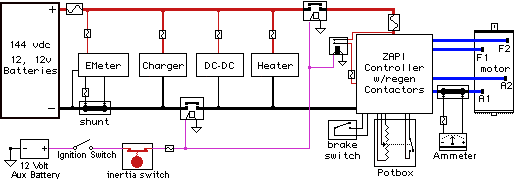
Here's the whole enchilada. I've included all of the fuses, contactors, relays and safety gear that I plan on installing. Major sub-assemblies or things that I d;Zapi with regen contactors, EMeter, and the heater schematics. In case it isn't obvious the things that look like an earthworm in a small box are fuses. Lots of those being used (fuses, not earthworms). I'm using two SW200 contactors, one on each leg of the main power as safety switches. These ensure that everything is disconnected when they key gets shut off or in the event of a significant enough impact to cause the Inertia Switch to open.
Oh, and once again I've left off some of the obvious connections like: 110 VAC plug for the Charger, 12vdc connection (car's battery) from the output of the DC-DC, and the suppression diodes across the relays. Somebody sent me email and asked where I was going to put the normal 12volt battery, since my layout pictures make it look too crowded for one. Well, I'm planning on using a small, lawn garden or motorcycle sized battery. This should be perfect since the battery is essentially a backup to the DC-DC converter. Besides: we don't need no stinkin' cold kin' amps!

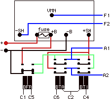
This is the Zapi and regen contactor wiring; the Zapi being the white square on the top. The rest of the wiring (potbox, etc...) is in the main schematic. There's some very small interconnect wiring that doesn't involve relays or other components that I'm not showing at all, or at least for right now. The way these contactors work is that they are pushed forward, or up, when energized. All contactors and relays on this page are shown in the OFF state.

EMeter Wiring
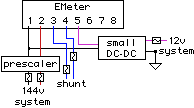
The EMeter wiring is a little bit strange since it is the one place where twelve volts and the 144 pack voltage come together. A relay or contactor easily isolates the twelve volts from the higher voltage, but in the case of the EMeter an additional component is required. The DC-DC converter pictured is a very small electronics package that stabilizes and isolates the car's 12 volt supply from the EMeter. Also there are a bunch of fuses, mostly in case anything goes wrong. The Emeter wiring enters the passenger compartment (behind the dash) and so we want to provide additional safety measures. The prescaler takes the 144vdc and scales (divides) it down to a range that the EMeter is designed to measure.

Heater Wiring
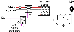
This is the first time I've included the heat circuitry in the schematics. It is pretty simple. The ceramic heater core gets its voltage from the 144v battery pack via a medium sized relay. I've slightly re-designed the car's heat system and added a switch for turning on the heat. Not only does it energize the relay so the heater core gets energized, but it ensures that the fan is running. The switch and fan to the right of the light green vertical line are the car's existing fan circuitry. The fan always has twelve volts applied when the key is on and the switch applies a ground to the resistors in series with the fan: the more resistors, the slower the fan turns, while zero resistance (far right) lets the fan spin at full speed. What I have done is exactly the same thing the A/C does (using the old A/C connector): force the fan to low speed whenever the heat is on. This way the fan can still be turned to higher speeds.
Next: Juggling
